

Article Figures & Data
Figures
- Figure 1.
Spine insertion point analysis in human pyramidal cell dendrites. A, Confocal microscope image showing an example of a labeled apical dendrite. For each individual dendritic spine, its point of insertion (white dots) in the dendritic shaft was manually determined. B, 3D reconstruction of each individual dendritic spine is shown in red. C, Projection image showing points of insertion in the same dendritic segment. Scale bar: (in C) A–D, 4 μm. D, Another example of a dendritic segment. E, Insertion point of spines (white dots) in the upper part of the dendritic segment shown in D. F, G, Straightening (F) and unrolling (G) tranformations to locate the 3D position of points in an unfolded arrangement (light blue dots). H, Area transformation to obtain an estimator of G(r). The unrolled distribution is “cut” by half (dotted line), and the pieces are “glued” to correct for edge effect bias. Note the new positions of neighbor points (circles and stars) after the new arrangement.
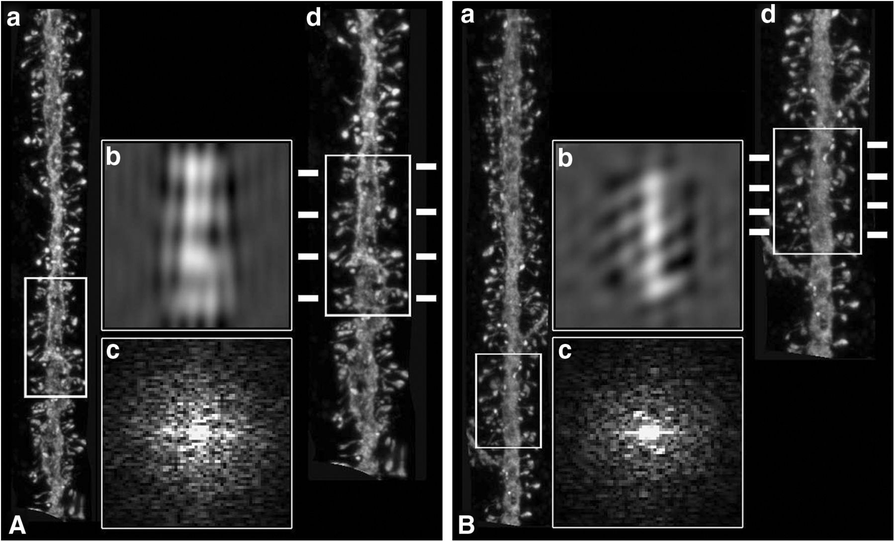
- Figure 2.
Fourier analysis. A, B, Two examples of dendritic segments from apical dendrites (a), showing regions in which helical distributions were apparent (white boxed areas), after the corresponding Fourier and inverse Fourier transforms (b, c). (d) Higher-magnification images of the same dendritic segments indicating possible frequency of regular spacing along the lateral insertion of dendritic spines (dashes).
- Figure 3.
Unstructured positioning of insertion points. A, D, Same dendritic segments as in Figure 2, along with points of insertion of spines (white dots). Red dots represent the white boxed areas from Figure 2, with potential spine helixes. B, E, Insertion points of dendritic spines of dendritic segments from A and D. C, F, Unfolded arrangement of the insertion points in B, E, after straightening (a) and unrolling (b). Artificial helical patterns, containing the same number of points as in the real dendrite, were created for comparison in each example (c). d, The corresponding unrolling process for the helical samples. G, H, Monte Carlo envelope tests of these examples. Graphs represent allowed random band (shaded), the theoretic distribution function GCSR(r) (red dotted line), and the estimated Ĝ(r) obtained from the patterns analyzed (black line) using the proposed edge correction. Because examples did not surpass the shaded envelope, the null hypothesis of complete spatial randomness (CSR) was not rejected.
- Figure 4.
Unstructured positioning of insertion points with different volume and lengths filters. A, Example of a basal dendritic segment. B, Insertion point of spines (white dots) in the same dendritic segment as in A. C, D, Straightening (C) and unrolling (D). E–H, Selective visualization of unfolded positioning of small (<0.3 μm3), large (>0.5 μm3), short (<1 μm), and long (>2 μm) spines using volume (E, F) and length (G, H) filters. I, Example of basal dendrite with insertion points of dendritic spines (black dots) along the distance from soma. J, K, Straightening (J) and unrolling (K) of I.


